
Zapper Construction on Principles by Hulda R. Clark
Douglas Duff
Many years ago I bought a book by Hulda Clark. I fashioned a "zapper" from basic prototype in her book. Then, I made several (at about 3 hours labor each) and gave to family members.
I was an over-the-road trucker that wouldn't leave home without "it" - the zapper, that is. If I were to pull into a dry, dusty, windy truck parking area in Laredo, Texas (for example), you know you'll be breathing dried dog feces from several blocks away; and, YOU'RE GONNA GET SICK. You'll start with a fever and soar throat; then, maybe nausea and vomiting.
Twenty minutes with my zapper and I'd be alright. If I had a soar throat, I'd hold one contact in my hand, the other in my mouth. Like I said, 20 minutes, soar throat gone. Otherwise, just one in each hand.
I drew out the diagram and made instructions so anyone can make a "zapper." The cost of material at Radio Shack (at that time) averaged out to about $25. It shouldn't be much more expensive now; plus, 3 hours of concentrated effort to put it together.
So, here's my gift to you. Use it as you will. There are no "trade" secrets involved; and, it was given by a Most Wonderful Scientist, Dr. Hulda Clark.
Doug Duff
********
PROCEDURE
Zapper Construction
on principles by HULDA R. CLARK
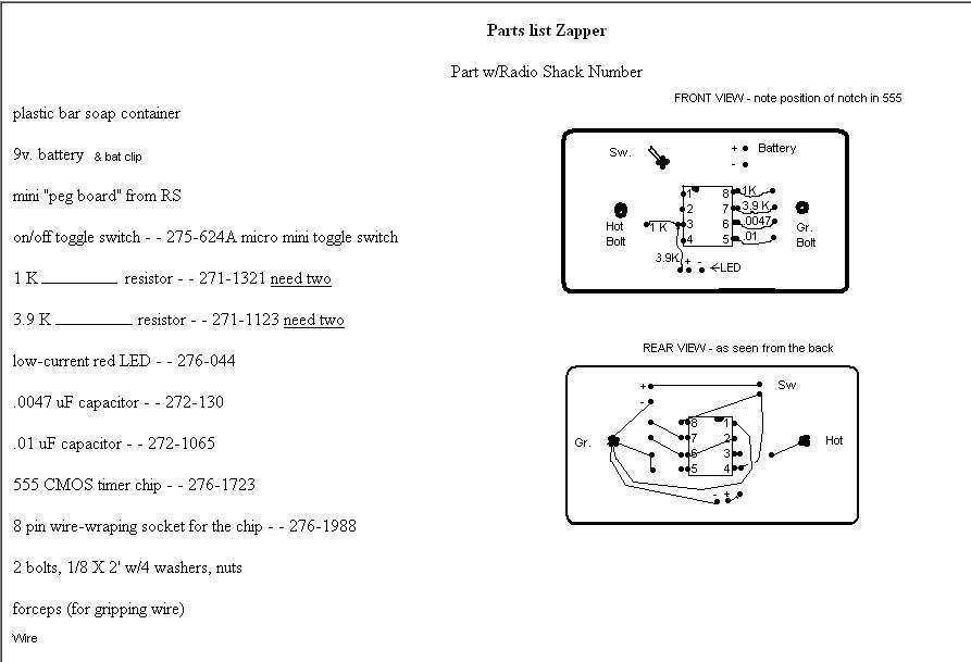
First, note position of "cookie bite" in 555 timer. It will always be positioned as seen in front view. It will be the last item installed before switch is turned on. Keep all metal, magnetics, soldering tips, etc. away from 555 timer. Handle only with dry fingers and/or toothpick.
Mount the wire wrap socket into your mini pegboard. Appropriate leads from resistors, capacitors, etc., can share the socket hole if convenient. Otherwise, place them in closest position to socket and wrap them as shown.
Begin by installing the .01 capacitor next to pin 5. Wrap to socket. Next, install .0047 capacitor next to pin 6, wrap it to socket. Mount the 3.9K resistor next to pin 7 and wrap. Mount the 1K resistor next to pin 8 and wrap.
Next to pin 3 mount the other 1K resistor (horizontally) and the other 3.9K resistor (vertically) in the same hole and wrap to pin 3. The 1K resistor protects the circuit if the terminals are accidentally shorted. The lower end of that 3.9K resistor is wrapped to the positive (the longer one) wire of the LED. The negative wire of the LED goes to the Grounding Bolt Terminal.
The free ends of the .01 and .0047 capacitors next to pins 5 and 6 are twisted together and connected to the grounding bolt terminal. Pin 2 and pin 6 are to be connected with a short wire and that connected to the free end of the 3.9 K resistor by pin 7.
The free end of the 1K resistor off pin 8 is then connected to pin 7.
From the lower terminal of the Switch, by wire connect to pin 8 and pin 4. Connect the other switch terminal to the + Positive battery terminal. The - Negative battery terminal is connected to the grounding bolt terminal.
The free end of the 1K resistor by pin 3 is connected to the HOT terminal.
Connect pin 1 to the grounding bolt terminal.
Gently install the 555 timer, pushing it into place until it "snaps", or at least has good contact. Pay attention to the position of the "cookie bite".
Install 9v battery, turn on switch. If the red LED comes on you've done everything right. Use alligator clips attached to HOT terminal and Grounding Bolt Terminal with leads connected to ss dinner knife, 30.06 shell casing, or other suitable hand-holds.
Zap 7 minutes an hour for 3 hours. Repeat daily, weekly, or as needed.
I simplified it for easy construction, but Hulda Clark (the most unselfish scientist I've ever studied after) engineered it. Doug Duff
***************